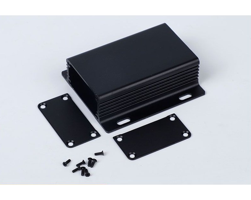
Why most first articles fail
Almost every failed first article we see comes down to missing information, not manufacturing error: a connector that needs 8 mm behind the panel, a board that will not slide past a boss, a gasket groove that was drawn but not toleranced.
This checklist is the one we walk through with customers before cutting metal.
1. Internal dimensions, not external
Start from the PCB and the tallest component. Add:
- 1.0–1.5 mm per side for a slide-in board (more if the board is long and the profile is bowed).
- 3 mm above the tallest component for the lid and any thermal pad.
- 6–8 mm behind panel-mounted connectors for the mating plug body and cable bend.
External size is the result, not the starting point.
2. Wall thickness
For 6063 extrusion, 1.5 mm walls are standard and 2.0 mm is available on most profiles. Going below 1.2 mm makes threads and gasket grooves unreliable. Going above 2.5 mm wastes weight and money without adding stiffness where it matters.
3. Mounting bosses and standoffs
Decide now: does the PCB screw into bosses that are part of the extrusion, or into standoffs pressed into the end plates, or float on a machined shelf? Boss height sets the internal stack-up and is the single most common thing to change late.
4. Cutout positions and datum
Give every cutout a position relative to one datum — usually the machined end face and one extrusion edge. Mixed datums are how holes end up 0.8 mm off and a connector will not seat.
5. Connector keep-outs
Draw the connector body, not just the hole. Include the latch swing, the cable exit direction and the bend radius. A USB-C port that fits the hole can still be unusable if the plug hits a fin.
6. Cable gland threads
Specify the standard (M12×1.5, M16×1.5, M20×1.5, PG7, PG9), the panel thickness at the entry, and whether a sealing washer is needed. If you are aiming for IP67, order the gland from a supplier that publishes an IP rating with the enclosure.
7. Gasket groove
For IP65 and above, draw a groove rather than a flat gasket face:
- Groove width = O-ring cord diameter × 1.25.
- Groove depth = cord diameter × 0.75.
- Corner radii at least 2× cord diameter.
- Screw spacing ≤ 50 mm on the gasketed joint.
8. Surface finish and colour
Pick one: mill finish, sandblasted, brushed, clear anodized, black anodized, or powder coated. Note where finish must be masked — sealing faces and grounding contact points need bare or chromate-converted aluminum.
9. Markings
Laser marking is cleanest on anodized surfaces; silkscreen or UV print works on powder coat. Give artwork as vector, note the marking area, and say whether it must survive solvent wiping.
10. Fasteners and assembly
Confirm screw type, thread (M3 × 0.5 is typical), torque, and whether you want captive screws. If the unit is field-serviceable, specify a quarter-turn or captive fastener now — retrofitting is expensive.
11. Environment and testing
Temperature range, IP target, vibration or drop requirement, and any EMC requirement. These change material, sealing and finish choices, so they belong in the first RFQ.
12. Volume and delivery shape
Annual volume, order pattern (one-off vs monthly releases), and whether you want kits (housing + gasket + screws + glands) or loose parts. Kitting is cheap at our end and saves you a receiving step.
Tolerances you can put on the drawing
| Feature | Typical tolerance |
|---|---|
| Cut length | ±0.3 mm |
| Machined cutout position | ±0.1 mm from machined datum |
| Hole diameter | +0.1 / 0 mm |
| Thread depth | ±0.5 mm |
| Flatness of sealing face | 0.1 mm |
| Surface roughness under gasket | Ra 1.6 |
The RFQ that gets a fast answer
Housing for 120 × 80 mm PCB, 22 mm internal height. Two M12×1.5 glands on the left end, one USB-C cutout on the right end per drawing. IP67, black anodized, laser logo on the top. 500 pcs first order, 2,000/yr. STEP and PDF attached.
With that, we can quote in a day and cut a sample in three.
FAQ
What file format should I send for a quote?
A STEP file plus a 2D PDF showing critical dimensions, thread callouts and surface finish. STEP alone forces us to guess tolerances; PDF alone forces us to remodel.
How much clearance do I need around the PCB?
Allow 1.0–1.5 mm per side to the inner wall for a slide-in board, and 6–8 mm at connector edges for the mating plug body plus cable bend radius.
What is a normal tolerance for CNC features on an extruded housing?
±0.1 mm on machined features referenced from a machined datum, ±0.3 mm on cut length, and ±0.5 mm on hole positions measured from an extrusion face.
Send us your housing spec
STEP or dimensioned PDF, target IP rating and annual volume. We answer with a price and a marked-up drawing — usually within one working day.